 wehub-resource-sync
I/O + Motor-Driver PCB (hardware / KiCad)
The custom board that connects every OOMWOO motor and sensor to the SBC: an STM32 MCU, motor drivers, sensor front-ends, and battery charging on one PCB. The MCU runs firmware / micro-ROS and talks to the Raspberry Pi 5 SBC over a serial / USB link.
Design basis: OOMWOO v1 uses a separate Raspberry Pi 5 as the SBC (ROS2, Nav2, SLAM), so this board is a pure I/O + power board — no application processor on it. There is a starting-point reference schematic (an RK3562 + STM32 combined design), but the on-board Rockchip SoC and its whole subsystem are removed; only the STM32 I/O side is kept and converted to KiCad for review.
References
-
Starting-point schematic (PDF) — makerspet/oomwoo-io-board. An RK3562 + STM32G070 reference (Apache-2.0, unvalidated — a starting point, not a proven design). Trim it down as described below.
-
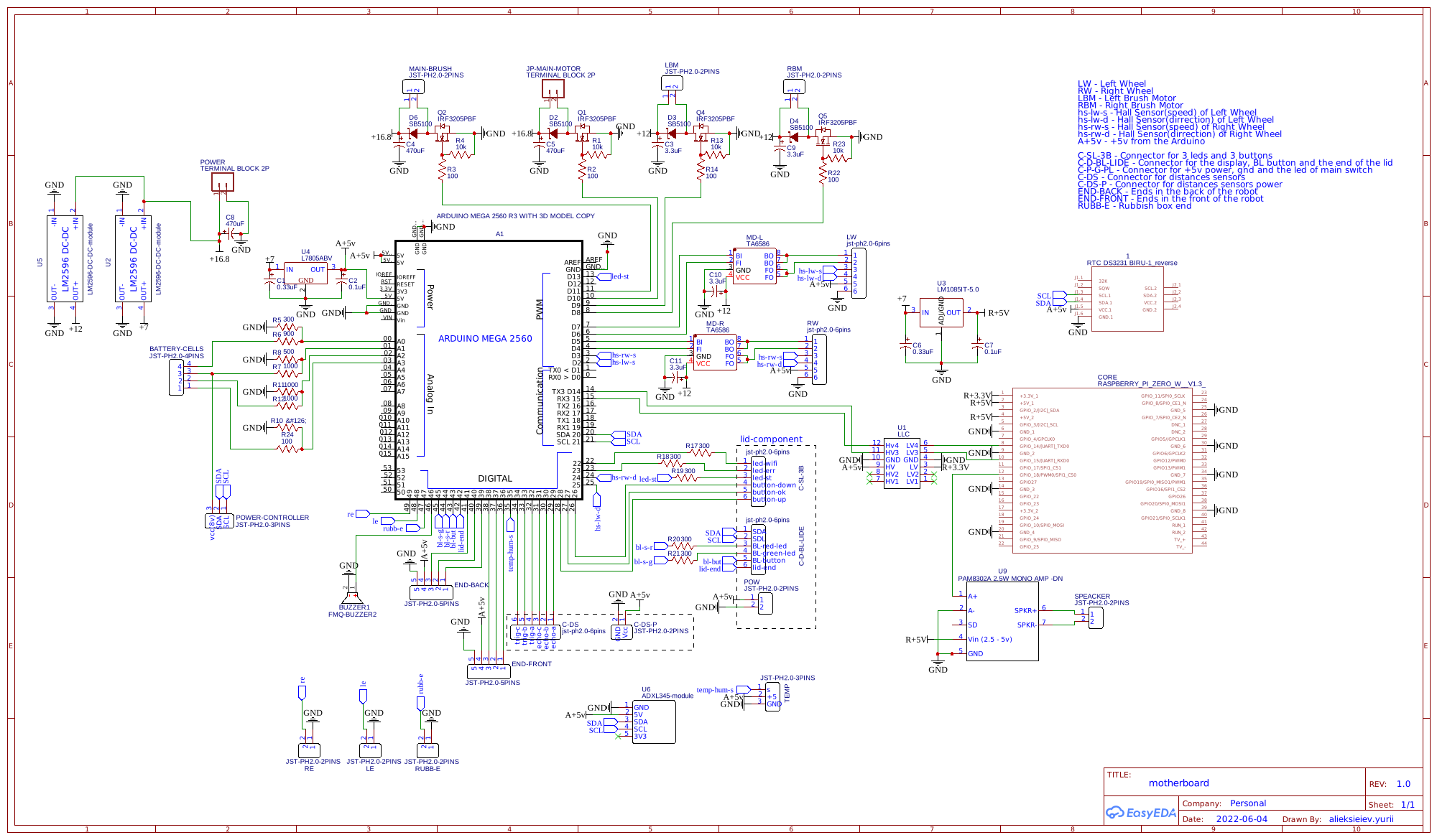
Drive-wheel connector pinout — AlieksieievYurii vacuum-cleaner motherboard schematic shows the drive-wheel assembly connectors: JST PH2.0, 6-pin —
Pin Signal 1 MOT+ 2 MOT- 3 HALL_SPEED 4 HALL_DIR 5 +5V 6 GND Verify against the sourced Roborock-family wheel module before layout — a submission in part-specs describes a variant with extra wheel-drop / limit-switch pins, so confirm the pin count and pinout on a physical module.
-
part-specs — connector pinouts, encoder PPR, and datasheets for the sourced parts.
-
design-document.md — the I/O-board section (MCU, pin budget, offloading the fan to an external ESC, etc.).
-
BOM.md — the sourced parts this board must drive.
Request for Contribution — Instructions
Deliver a KiCad schematic derived from the reference PDF, trimmed to the I/O side and updated for OOMWOO, then hold for review before PCB layout.
- Remove the Rockchip subsystem entirely — the RK3562 SoC and everything that exists only to support it: LPDDR4 DRAM, eMMC, the SoC PMIC / SoC-specific power rails (VCCIO, PMU / OSC / PLL), the DDR PHY, the USB / PCIe PHY, and the MIPI camera interface. Heavy compute and the camera live on the Raspberry Pi 5 SBC, not this board.
- Remove the WiFi / BT module (AP6256) — WiFi/BT is provided by the SBC.
- Keep and convert to KiCad the I/O side:
- STM32G070 MCU + support (clock, decoupling, debug / boot, the serial / USB link to the SBC)
- motor drivers — drive wheels (×2), main brush, side brush, water pump, mop lift / spin (if fitted); put the suction fan on an external ESC (one PWM line) to save MCU pins
- sensor front-ends — cliff / anti-fall IR, docking IR + bumper, side-proximity IR, bumper switches, IMU, LiDAR interface, multizone ToF, ultrasonic carpet sensor
- battery charging + protection / BMS, and the board power rails that feed the STM32 / sensors / motors (keep these; remove only the SoC-specific rails)
- speaker + amp, mic, buttons, LEDs
- Move the battery from 3S to 4S — OOMWOO targets ~14.8 V (see BOM.md). The reference appears to be 3S; update the pack, the charge-IC configuration, the protection, and any cell-count-dependent dividers / thresholds to 4S.
- Wire the drive-wheel connectors to the JST PH2.0 6-pin pinout above (verified against the sourced module).
- assume battery Xiaomi/Roborock/Dreame BRR-2P4S-5200
- Convert the kept design to KiCad (from Altium); keep a clean, readable, hierarchical schematic.
- Hold here for review. Deliver the trimmed, 4S, KiCad schematic and stop — the maintainer reviews before anyone starts PCB layout / manufacturing.
- Submit a PR to
contributions/io-pcb/<your-github-username>/with the KiCad project, a short sub-BoM, and notes; announce it in Project Discussions. - iterate with review
- TBD, expect the RFC to evolve
Acceptance criteria (schematic-hold milestone)
- The entire Rockchip subsystem (SoC, DRAM, eMMC, PMIC / VCCIO / PMU / PLL, DDR + USB/PCIe PHY, MIPI camera) and the WiFi / BT module are removed.
- The kept blocks (STM32G070, motor drivers, sensor front-ends, battery charging, audio, buttons / LEDs, SBC link) are present, correct, and complete in KiCad.
- Battery as specified
- Drive-wheel connectors match the referenced pinout (JST PH2.0 6-pin), reconciled with part-specs.
- Delivered as a buildable KiCad project; ERC clean; a sub-BoM and short design notes included.
- Stops at the reviewed schematic — no PCB layout yet.
- Documented and reproducible.
- TBD, expect criteria to evolve.
The maintainer intends to accelerate this module and may commission a contributor to do it; community submissions are still welcome and reviewed the same way. The maintainer selects among compliant candidates using these criteria — multiple attempts are welcome and useful even if not selected.
Appendix A. Tentative MCU GPIO list
- Power source current sense (analog in)
- VBat sense (analog in)
- Main fan sense (analog in)
- anti-fall left up sensor (analog in because IR sensors are analog)
- anti-fall left down sensor (analog in)
- anti-fall right up sensor (analog in)
- anti-fall right down sensor (analog in)
- wheel motor left driver in1 (digital output)
- wheel motor left driver in2 (digital output)
- wheel motor left driver encoder (digital input)
- wheel motor right driver encoder (digital input)
- Power button (digital input)
- CPU (e.g. Raspberry Pi) power on/off (digital output)
- STM32 SWDIO
- STM32 SWCLK
- Vacuum power on/off (digital output)
- Wheel motor right current sense (analog in)
- Wheel motor left current sense (analog in)
- Main brush motor current sense (analog in)
- IMU SPI SCLK (digital out)
- IMU SPI MISO
- IMU SPI MOSI
- IMU SPI CS
- Wheel motor right driver in1 (digital out)
- Motors power enable (digital out)
- Wheel motor right driver in2 (digital out)
- Water pump sense (analog in)
- Side brush left front motor sense (analog in)
- Side brush right front motor sense (analog in)
- CPU reset (e.g. Raspberry Pi)
- Dock IR sensor 1 (analog in)
- Dock IR sensor 2 (analog in)
- Water pump motor PWM (digital out)
- Main brush motor PWM (digital out)
- Lidar motor PWM (digital out)
- Bumper switch 1 (digital in)
- UART1 TX
- UART RX
- Side brush motor right PWM (digital out)
- Side brush motor left PWM (digital out)
- Power LED on/off (digital out)
- Home LED on/off (digital out)
- Home button (digital in)
- Battery charge sense (digital in)
- Charge status (digital out)
- Bumper switch 1 (digital in)
- Bumper switch 2 (digital in)
- Test/program
- Test/program
- Main fan motor PWM (digital out)
- Main fan motor current sense (analog in)
- IMU interrupt 2 (digital in)
- IMU interrupt 1 (digital in)
- IMU FSYNC (digital in)
- Side proximity IR sensor left (analog in)
- Side proximity IR sensor right (analog in)
- Side proximity IR LED left PWM (digital out)
- Side proximity IR LED right PWM (digital out)
- Wheel drop sensor left (digital in)
- Wheel drop sensor right (digital in)